Fri, 02/09/2007 - 02:00
How to add an LED indicator light to your cooling fans
Okay, let me begin with this statement: I know nothing about electronics, so if something works once I'm done, I just start counting days to see how long it will last. *sigh*
Sometimes when I turn on my IceCap fans to cool the tank down, I forget and leave them running. I can't use the Aqua Controller II to turn them on and off because the x-10 technology burns up the DC power supplies. I only have to use them occasionally, but there are nights when I wonder why the tank is down to 79F or less. The IceCap fans are so quiet when running in the lowest mode, I don't hear them. Usually the next day I'll figure it out when the lights are on and I hear them spinning at warp speed.
So, I wanted to add a LED to just give me a clue if they are running. That way when I walk by at 3am, I'd have an indicator to remind me to shut them off if necessary. I asked some DFWMAS members for some help, and Russ talked me through it. Thanks to Russ' help, I have a working LED now. Here are all the pictures.
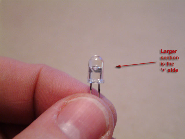
First of all, let me tell you it is SO easy to blow out an LED, I can't believe it. Russ was helping me ascertain which side was the positive side on a 9v battery (via telephone). Sounds simple, right? It turned on for a split second and that was the end of that $1.49 LED. My fault, since I wasn't using the resistor during the test.
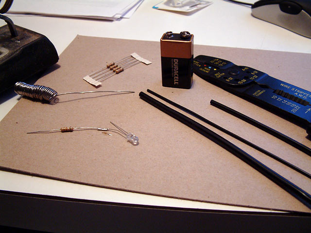
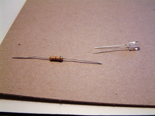
Okay, so here are my parts. The resistors and two LEDs were under $5 from Radio Shack. Take note, I was told to use a 600 Ohm resistor, but they didn't have them so I got 680. I figured the bulb would be a tad dimmer as it wouldn't get as much juice. I was right.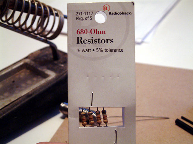
The LEDs weren't 3.3V as recommended either. They were 1.7V, but I was told the more important part was 20mA anyway.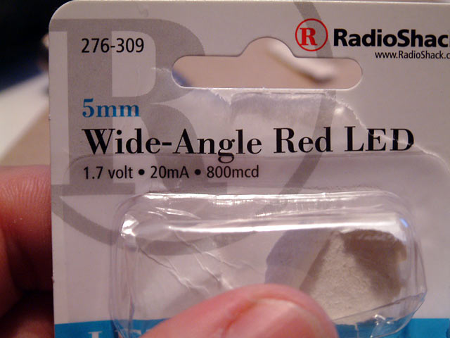
I got out my tools. Soldering iron, heat shrink tubing, etc.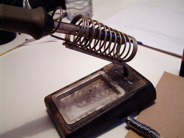
I have a feeling if you leave the soldering iron on the LED too long, you'll send too much heat up the diode's wire and cook it. I tried to work fast, and it was a tad sloppy. Here's the first solder, connecting the 680 Ohm resistor to the positive side of the LED.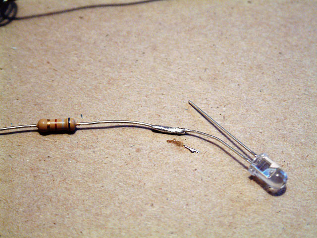
Then I connected the other end of the resistor to the positive wire going to the power supply.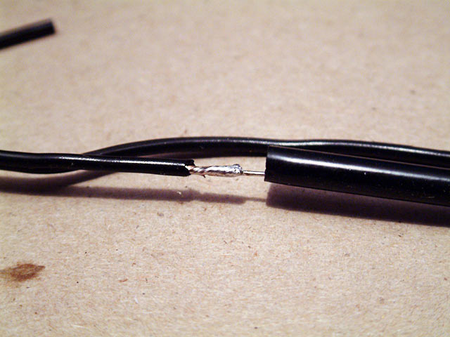
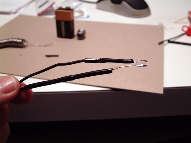
Soldering on the other side, quickly yet again.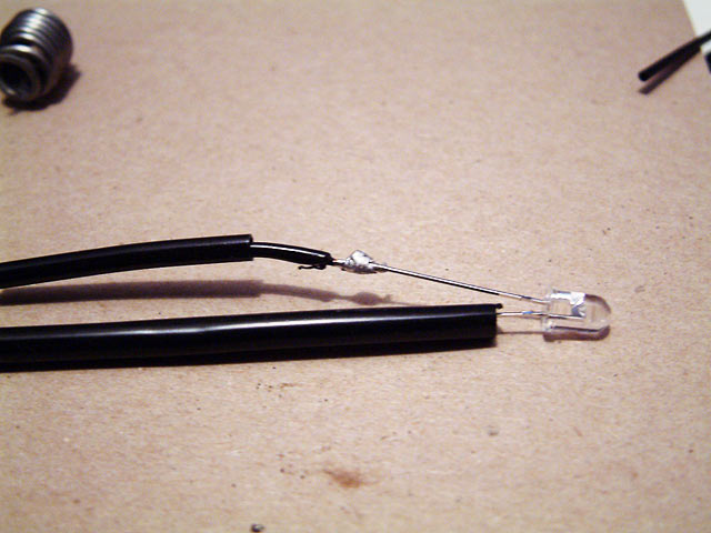
Quick test.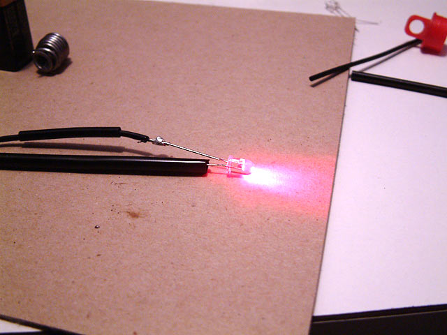
Next, I used a candle's flame to shrink the tubing over the soldered connections. Just keep it moving over the flame, never too long in one spot.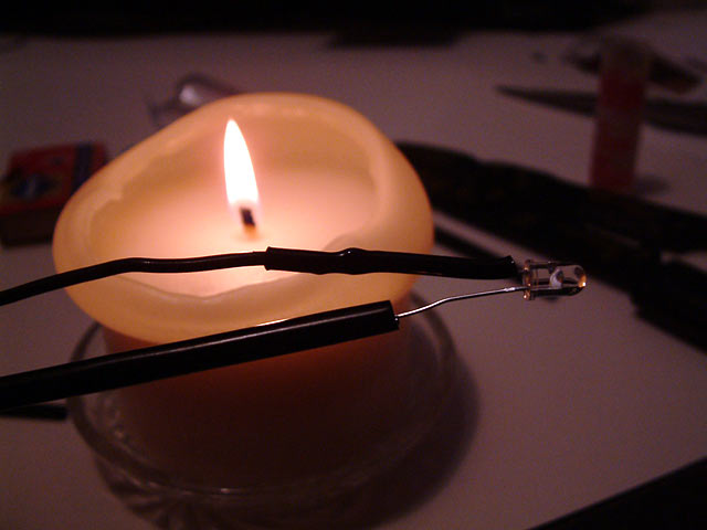
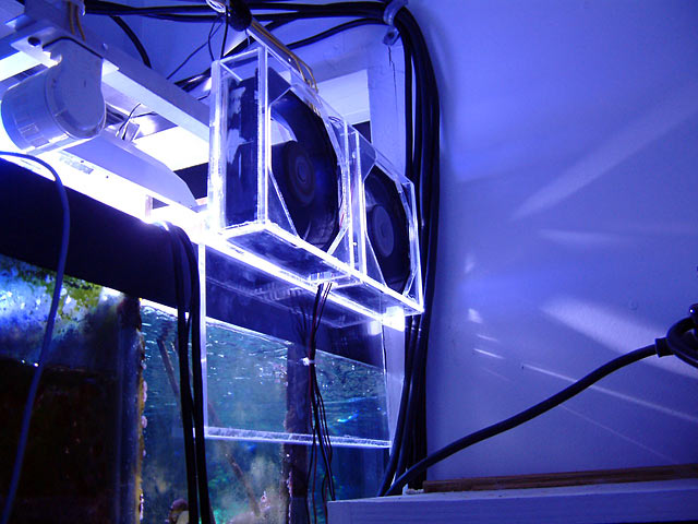
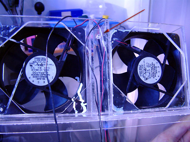
Once done, I had to drill a hole in the fan bracket to hold the LED in position. This is an older bracket I made a long time ago, back when looks didn't count. The LED is clear, so it is almost invisible in this image, facing directly at the viewer.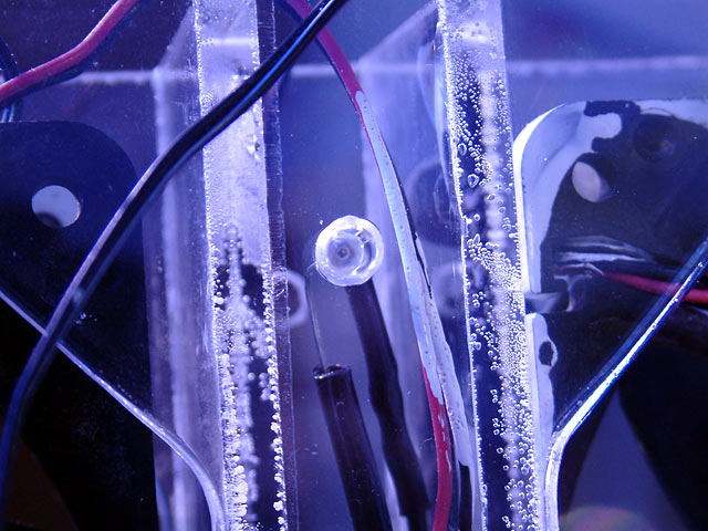
From the backside.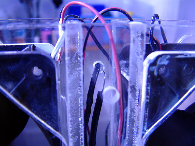
The power supplies are a mess, but it is what it is. One runs one fan, and the other runs the fan with the new LED.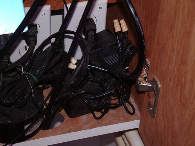
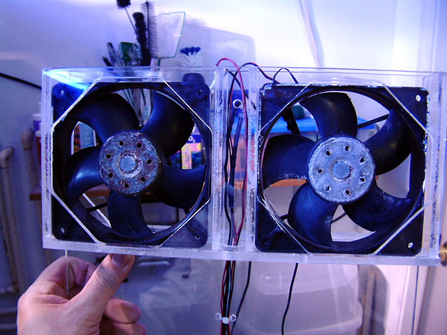
And turned on.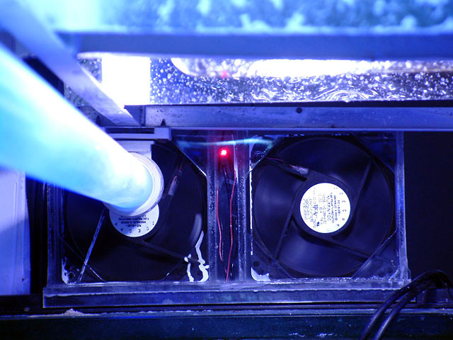
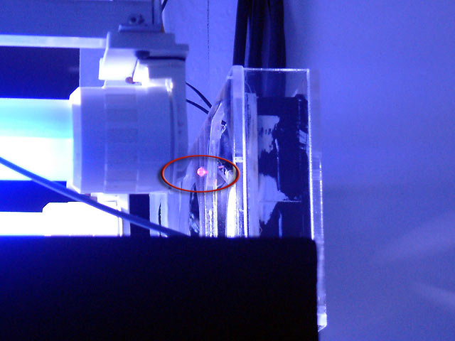
Done!